Reza Ikhlasul
February 16, 2011
Prerequisites: CCNP level skills.
Cisco IOS OSPF modes:
- Point-to-point (Cisco)
- Broadcast (Cisco)
- Non-broadcast (RFC 2328)
- Point-to-multipoint (RFC 2328)
- Point-to-multipoint non-broadcast (Cisco)
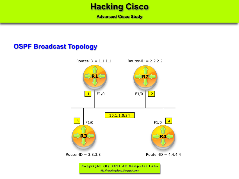
Topology
Pic. 1 - Topology Diagram.

Workflow
Lab Solution
Note!
Lab is similar to Lab 4 (previous post). The only difference is the mandatory 'neighbor' statement on R1. Except for that, the behavior is just like on point-to-multipoint networks.
R1 Configuration:
R2 Configuration:
R3 Configuration:
Verification
Note!
The verification steps as per Lab04.

Icons designed by: Andrzej Szoblik - http://www.newo.pl
Workflow
- Get familiar with the topology.
- Read the 'Task List'.
- Read the 'Questions' and provide the answers BEFORE configuring the routers.
- Configure the lab according to the 'Task List' .
- Compare the answers (step 3) with the lab results.
- Configure IP addresses as per topology diagram and use encapsulation Frame-Relay on S0/0 interfaces.
- Make sure that you use only DLCIs specified in the topology diagram (pic. 1) and routers do not learn any other other DLCIs dynamically.
- Assume that pseudo broadcast is not supported.
- Configure OSPF with all links in area 0. Make sure that R2 can ping R3's loopback0 and S0/0 interfaces (no additional layer 3 to layer 2 mappings).
- What is the behavior of OSPF point-to-multipoint non-broadcast mode compared to non-broadcast on Frame-Relay links?
- How does point-to-multipoint mode differ from point-to-multipoint non-broadcast OSPF mode?
- What are the default hello/dead interval timers on point-to-multipoint non-broadcast links?
- What is going to be the next-hop address on R2 for 172.16.103.0/24 using point-to-multipoint links? Why?
Lab Solution
Note!
Lab is similar to Lab 4 (previous post). The only difference is the mandatory 'neighbor' statement on R1. Except for that, the behavior is just like on point-to-multipoint networks.
R1 Configuration:
!
interface loopback0
ip address 172.16.101.1 255.255.255.0
ip ospf network point-to-point
!
ip ospf network point-to-point
!
interface Serial0/0
ip address 10.1.1.1 255.255.255.0
encapsulation frame-relay
ip ospf network point-to-multipoint non-broadcast
frame-relay map ip 10.1.1.2 102
frame-relay map ip 10.1.1.3 103
no frame-relay inverse-arp
!
ip address 10.1.1.1 255.255.255.0
encapsulation frame-relay
ip ospf network point-to-multipoint non-broadcast
frame-relay map ip 10.1.1.2 102
frame-relay map ip 10.1.1.3 103
no frame-relay inverse-arp
!
router ospf 1
router-id 1.1.1.1
log-adjacency-changes
network 10.1.1.1 0.0.0.0 area 0
network 172.16.101.1 0.0.0.0 area 0
neighbor 10.1.1.3
neighbor 10.1.1.2
!
router-id 1.1.1.1
log-adjacency-changes
network 10.1.1.1 0.0.0.0 area 0
network 172.16.101.1 0.0.0.0 area 0
neighbor 10.1.1.3
neighbor 10.1.1.2
!
R2 Configuration:
!
interface loopback0
ip address 172.16.102.2 255.255.255.0
ip ospf network point-to-point
!
ip ospf network point-to-point
!
interface Serial0/0
ip address 10.1.1.2 255.255.255.0
encapsulation frame-relay
ip ospf network point-to-multipoint non-broadcast
frame-relay map ip 10.1.1.1 201
no frame-relay inverse-arp
!
ip address 10.1.1.2 255.255.255.0
encapsulation frame-relay
ip ospf network point-to-multipoint non-broadcast
frame-relay map ip 10.1.1.1 201
no frame-relay inverse-arp
!
router ospf 1
router-id 2.2.2.2
log-adjacency-changes
network 10.1.1.2 0.0.0.0 area 0
network 172.16.102.2 0.0.0.0 area 0
!
router-id 2.2.2.2
log-adjacency-changes
network 10.1.1.2 0.0.0.0 area 0
network 172.16.102.2 0.0.0.0 area 0
!
R3 Configuration:
!
interface loopback0
ip address 172.16.103.3 255.255.255.0
ip ospf network point-to-point
!
ip ospf network point-to-point
!
interface Serial0/0
ip address 10.1.1.3 255.255.255.0
encapsulation frame-relay
ip ospf network point-to-multipoint non-broadcast
frame-relay map ip 10.1.1.1 301
no frame-relay inverse-arp
!
ip address 10.1.1.3 255.255.255.0
encapsulation frame-relay
ip ospf network point-to-multipoint non-broadcast
frame-relay map ip 10.1.1.1 301
no frame-relay inverse-arp
!
router ospf 1
router-id 3.3.3.3
log-adjacency-changes
network 10.1.1.3 0.0.0.0 area 0
network 172.16.103.3 0.0.0.0 area 0
!
router-id 3.3.3.3
log-adjacency-changes
network 10.1.1.3 0.0.0.0 area 0
network 172.16.103.3 0.0.0.0 area 0
!
Verification
Note!
The verification steps as per Lab04.


